
The Compact Reconnaissance Imaging Spectrometer for Mars (CRISM) is a Visible and Near-Infrared (VNIR) imaging spectrometer onboard Mars Reconnaissance Orbiter (MRO), in orbit since 2006. It was built and tested by the Johns Hopkins University Applied Physics Laboratory under the supervision of principal investigator Scott Murchie. The observations enable to have mineralogy information of the martian surface at a spatial resolution of ~20 to ~200 m/px.
Data description
The CRISM instrument has two acquisition modes:
The targeted mode (multiangular pointing)
The instrument tracks the targets and takes 11 hyperspectral images (544 bands from 362 to 3920 nm) at different emission angles due to the rotation of the detector at ± 70°: 10 hyperspectral images taken at different emission angles before and after the central image corresponding to the close nadir image (image #07). The 10 hyperspectral multi-angular observations are reduced to a factor 10 compared to the spatial resolution of the central image. According to the spatial resolution of the central image, four product types are associated to this acquisition mode. If the central image is sampled at 20 m/px, the associated product is a Full Resolution Targeted observation (FRT). By reducing the spatial resolution of the central image by a factor 2, the spatial resolution is set at 40 m/px and the associated products are Half Resolution Short (HRS) and Half Resolution Long (HRL) observations. An HRL sampled surface is twice as long as an HRS observation. Only the central image #07 is processed by MarsSI for the mineralogy identification. ATO observations are Along-Track Oversampled products resulting in incresing of the resolution up to 3 m/px.
| Types of targeted observations | |||
| FRT: 18 m/px | HRS: 36 m/px | HRL: 36 m/px | ATO: 3-12 m/px |
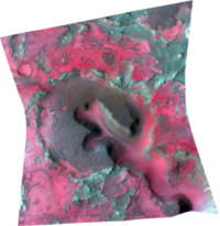 | 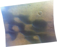 | 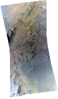 |  |
The survey mode (nadir pointing)
This mode was designed to estimate key locations for further analysis with the targeted mode as it covers wider areas and produces lower spatial resolution data than the targeted mode. The instrument acquires multispectral images using fixed pointing where the emission angle is set at 0° (with specific bands chosen over the 544 spectral bands, in order to identify principal minerals). There are different types of observations using this acquisition mode:
- Multispectral Survey (MSP): 200 m/px and 55 channels
- Hyperspectral Survey (HSP): 200 m/px and 154 channels
- Multispectral Window (MSW): 100 m/px
Processing CRISM data
From the “Maps” tab, zoom-in on your region of interest, you can display the THEMIS mosaic for more precision, and then display the CRISM FRTHRLHRS07 layer corresponding to the central image of the targeted sequence. You get all CRISM stamps that appear in red. You can use the “Select” button to choose the stamp you desire. You can choose several stamps by clicking on several stamps, or by dragging your mouse to select adjacent stamps. You can also use the “Search” button for more options.
To add your desired stamps to your cart click on “Add” in the “Cart” window: you can notice in the “Cart” window that different data were added: the TRDR files and the DDR files in Short (VNIR) and Long (IR) wavelength ranges, “S” and “L”. Only the “L” cubes are used in the CRISM processing and are needed for further processing in MarsSI, but you can also download the “S” cubes for your own use. Then, go to the “Workspace” tab.
Your CRISM TRDR and DDR “L” files appear in the window “Data to process”. If not, you may already have processed them yourself, or someone else may have processed them, then they may already be in the “Data processed” window. If the data have not been processed, you will have to go download and process the TRDR and DDR cubes by clicking on the “Process” button in the “Data to process” button.
The TRDR cube containing the reflectance values in the infrared range will be processed using an implementation of the CAT pipeline (CRISM Analysis Tools, an add-on to IDL/ENVI available from the CRISM team (Murchie et al., 2007; Pelkey et al., 2007)). The cube will be corrected for the observation geometry (reflectance divided by the cosine of the incidence angle, available in the associated DDR cube) and for absorptions due to atmospheric CO2 using the CAT algorithm developed for CRISM based on the ‘volcano-scan’ approach (McGuire et al., 2009).
Data names
The CRISM naming convention is the following:
(ClassType)(ObsID)_(Counter)_(Activity)(SensorID)_(Filetype).(EXT)
ClassType: FRT, HRS, HRL, ATO, MSP, HSP, MSW, ...ObsID: observation IDCounter: image number of the targeted sequence (only the n°7 is used in MarsSI). In the survey mode, this corresponds to 1Activity: subtype of product: IF stands for reflectance data (I/F unit), DE for ancillary data (e.g. latitude, longitude, incidence, emission, phase angleSensorID: S detector (Short wavelenghts) or L (Long wavelenghts)Filetype: type of dataset: TRR3 are calibrated data cubes, DDR1 companion data cube containing the ancillary data
Ex: FRT000A82E_07_IF164L_TRR3.IMG correponds to calibrated data cube containing the reflectance data (I/F unit) in the IR range (from 1002 to 3920 nm) of the central image (corresponding to the “07” image of the targeted sequence) of an FRT observation.